Finishing tab allows you to set [Bleed], [Grommets], and [Marks] on your images.
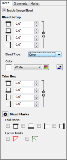
The Bleeds can easily be added to an image. You can set following options checking [Enable Image Bleed].
Bleed Setup
By default top, bottom, left, and right bleed values are locked. To set the values independently, unlock them by clicking the link icon. Changed bleed values are reflected in an update to the print size values. The default bleed sizes are set to “0”.
- Top: This will expand the top of your image. You can adjust the value or enter a custom value.
- Bottom: This will expand the bottom of your image. You can adjust the value or enter a custom value.
- Left: This will expand the left side of your image. You can adjust the value or enter a custom value.
- Right: This will expand the right side of your image. You can adjust the value or enter a custom value.
Bleed Type
There are 3 types of bleed. You can choose following options from pull down menu.
- [Color] fills the bleed with a certain color. The default color is [White], but you can select [Cusrom…] option entering each value clicking
button or using the color picker on the [Color] option. [Color] also has a [First Pixel] option that will find the first pixel of the image and set the entire bleed to that color.
- [Mirror] will make a mirror copy of your image and fill it into your bleed. The default setting is 0.25 inch (5 mm) with fold marks, and a displayed image has 1 inch (25.4 mm) bleed.
- [Duplication] fills the bleed with the colors from the each edge of the original image.
Trim Box
This option makes extra white space in outside of bleed. By default top, bottom, left, and right bleed values are locked. To set the values independently, unlock them by clicking the link icon and enter value for [Top], [Bottom], [Left] and [Right].
Bleed Marks
This option creates additional lines that assist for finishing work. Open “Setup Mark Line Style” dialog (Figure 2) clicking
Line Type: There are 3 types of lines.
- Solid Line - You can set [Line Width] and [Line color].
- Dotted Line - You can set [Line Length], [Gap Length], [Line Width] and [Black] or [White] color.
- Alternative Line - You can set [Line Length], [Gap Length], and [Line Width].
Fold Marks – This option generates fold lines between bleed and an image. By default, [Top], [Bottom], [Left], and [Right] are checked.
Edge Marks – This option generates diagonal line in each corner of an image for fold. Select [Corner Marks] or [Frame Corner Marks].
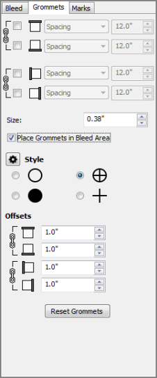
This option can easily be added Grommets to an image. By default the top and bottom, as well as left and right values are locked together. To set the values independently, unlock them by clicking the link icon (Figure 3).
Spacing– This allows you to specify an approximate distance between grommet marks on a side of the image. The first and last mark locations will be determined by the offsets one either side, then marks will be added between them as needed, using the distance specified as a guide.
Quantity - This allows you to specify the number of grommet marks to place on a side of the image. The first and last mark locations will be determined by the offsets, then marks will be added at evenly-spaced intervals between them.
Grommet Mark Size
This option allows you to set a size for grommet marks. Mark Size measurement will be the diameter of the circle or the length of the cross-hairs, depending on the style selected.
Grommet Mark Style
There are four grommet mark styles: a circle, a filled-in circle, cross-hairs, or a circle with cross-hairs.
To make changes to the line type, width, or color, use the settings button to open the “Setup Mark Line Style” dialog.
To use the Grommet option:
- To add grommet marks, check a mark to [Top], [Bottom], [Left] and [Right], or any combination of designed settings.
- Set a grommet size that you want.
- Select grommet mark style from 4 styles and click
button for setting mark line style. This will open "Setup Mark Line Style" dialog. You can specify the space between grommet marks in the [Gap Length] option of this dialog (Figure 2).
- Enter custom value that you want to make space from cutting line of an image.
You can reset all settings by click [Reset Grommets] button.
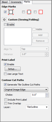
The [Marks] option allows you to determine the marks that will be used with your image. Marks assist you in cutting, welding, and framing your finished job (Figure 3).
You can also set up the Print Label from the [Marks] option. The [Print Label] contains information about your job such as resolution, size, date printed, and so on. This information is printed with your image in one of the margins and can help you recreate the image at a later date.
To use the Marks option:
(In Job Editor)
1. Open the Marks option by clicking [Finishing] tab and select [Marks] tab.
2. Select the Marks that you want to use by selecting the appropriate options.
3. If you want to use the Print Label, enable that option and click [Setup] button. This opens the “Print Label Setup” dialog.
4. Select your options and type required information for the Print Label, and Click [OK.]
(In RIP-Queue)
You also can set Marks option in the Quick Sets .
1. In the RIP-Queue, go to Edit Quick Sets icon and clicking Edit > Advanced > Finishing > Mark from the tree.
2. Check a mark the types of marks to want to use by selecting the appropriate options.
3. If you want to use the [Print Label], enable that option and click [Setup]. This opens the”Print Label Setup” dialog.
4. Select your options and type required information for the Print Label, and Click [OK].
The [Marks] option includes the following settings:
Edge Marks
[Edge marks] option has 3 types of mark: Registration Mark, Crop Mark, Crop Outline. Check a box you want to use.
- Registration marks print a crosshair mark at each corner of an image. These marks help ensure that the image is straight on each side when trimming.
- Crop marks are right-angle marks that are placed on the edges of each corner of the image. Because the same area is used for Registration marks, Crop marks do not have any effect if you are already using Registration marks.
- Crop Outline prints a solid line around the border of the entire image. When using [Crop Outline], the Crop marks have no effect because the solid line is printed in the same area as the Crop marks.
Custom (Sewing/Folding)
This option allows you to set [Sewing] marks and [Folding] marks in custom locations on the image. The default is set to add lines to all sides of the image, at a distance 1 inch (25.4 mm) from the edges.
To use Sewing / Folding Marks
- Check a box of the [Enable Sewing Marks] for set any options you want to use.
- Click
button for setting up mark line style. You can set [Line Type], [Line Length], [Gap Length], [Line Width], and [Line Color] in the “Setup Mark Line Style” dialog (Figure 2).
- Select alignment you want to place sewing / folding Marks on your image.
Visible Sewing / Folding Marks:
Check [Visible] box so that the sewing marks will be visible in the preview and printed on the job. If the box is not checked, nothing will be printed for this sewing mark. This option may be used when you need to see where a specific mark is by turning it on or off. You may also have a sewing mark saved to use later and need it temporarily turned off.
To add a new mark:
Click [Add] button. This will add a new mark from the left side.
To change a mark placement:
To change the placement of that mark, make sure it is highlighted, then select from the [Align To] drop-down menu to align the mark to the [Top], [Left], [Bottom], or [Right].
To change a mark distance:
To change the distance from the selected edge, click the arrows or type in the desired measurement. The default setting is 1.0 inch (25.4 mm).
To remove a mark:
Click to highlight the mark you want to remove, then click [Remove] button.
Print Label
The [Print Label] prints job information at the end of the printed image.
To use the Print label, check a box of [Enable], and click [Setup]. You can then select the type of information you want to include in your Print Label by scanning through and marking the appropriate options.
Contour Cut Paths
This option determines where the Tile Outline Cut will be created. Check the [Generate The Outline Cut Paths] box select the following options. In default setting is checked [Original Image Edge].
- Original Image Edge - This option generates a cut path around the original image area.
- Bleed Edge - This option generates a cut path around the bleed area.
- Trim Box Edge - This option generates a cut path around the trim area.
NOTE: If you do not have a contour cutting device, this option will not work.
Choke
[Choke] modifies the cut path by moving the path inside the edge by the chosen distance.
Trim Overlap
This option configures RIP-Queue to place cut lines in the center of the overlap.
TIP: To learn more about Finishing Tool, see a white paper .

Figure 1

Figure 2

Figure 3
 Bleed
Bleed